Software
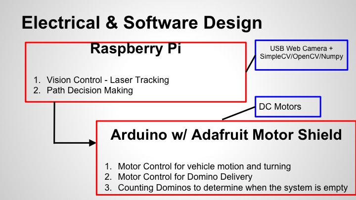
The above diagram shows an overview of the software architecture running on Dominobot. The software can be split up into two main components: The python modules running on the Raspberry Pi and the code running on the Arduino.
Raspberry Pi Software

The Raspberry Pi is primarily responsible for computer vision and path decision making. Driving these capabilities is the use of OpenCV, SimpleCV as well as NumPy. Computer vision is used to determine the position of the laser in the image frame and this position is then used to make decisions about how to drive the robot.
Detection of the laser is done by first using OpenCV to set the camera settings such that saturation is turned up and brightness is turned down. Turning up saturation intensifies the color in the image and exaggerates the Red-Green-Blue (RGB) values. This makes it easier for us to filter the image later. Turning down the brightness minimizes the chance that other red objects in the room will get detected; the laser is far brighter than any other objects in the camera's field of view. The image below is an example of what the Raspberry Pi 'sees':
Detection of the laser is done by first using OpenCV to set the camera settings such that saturation is turned up and brightness is turned down. Turning up saturation intensifies the color in the image and exaggerates the Red-Green-Blue (RGB) values. This makes it easier for us to filter the image later. Turning down the brightness minimizes the chance that other red objects in the room will get detected; the laser is far brighter than any other objects in the camera's field of view. The image below is an example of what the Raspberry Pi 'sees':
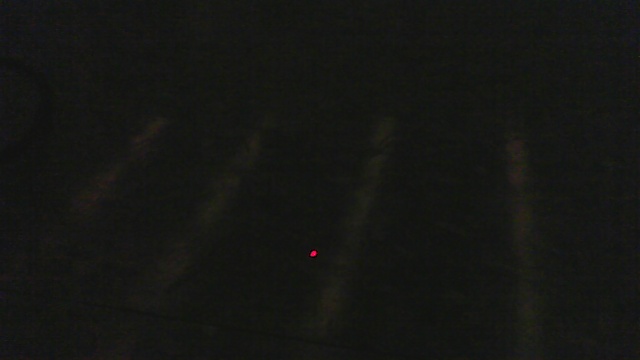
This is an example of what the Raspberry Pi 'sees'. The laser dot is very prominent, streamlining the image processing.

We then use SimpleCV to take a picture of the scene in front of the robot. This image then undergoes the following processes:
- SimpleCV functions are used to retrieve the arrays representing the red, green and blue values in the image. These are returned as NumPy arrays
- The NumPy array representing the image's red channel is searched to find the pixels in which the image is the 'most red'
- Next, the software checks the 'most red' pixels' blue and green values. This check makes sure that our 'red' values are indeed red, as opposed to white, yellow, etc. We empirically determined environment-specific threshold valuesIn the case of our specific environment and camera, we discovered that in order to correctly detect the laser, the blue threshold value had to be set at approximately the midpoint while the green threshold value could be set very low. Using these settings, we obtained a reasonably accurate way to detect the laser pointer.
- Each point that satisfies the above criteria for red, green and blue values is then returned as an x and y co-ordinate, corresponding to the number of pixels in the image in each direction.
- Because we expect to obtain a cluster of points, we assume that the software will only find points that are approximately in the same cluster. Thus we simply take the average co-ordinate value from all co-ordinates returned and use that as the position of the laser.
The output image from the software is shown below:
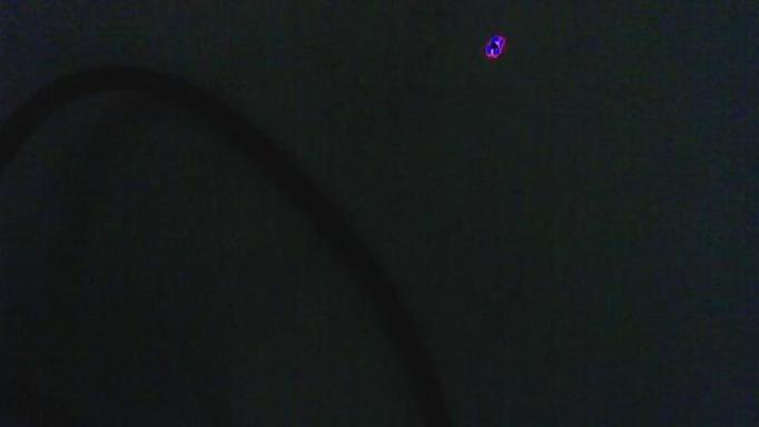
Output Image from the Software After Processing & Filtering
Our software carries out the above steps as many times as is necessary in order to obtain 3 sets of co-ordinates that are not equal to (0,0). It then takes the average of these three to obtain a final position of the laser. This is done in order to try to eliminate or average out false readings.
A video of a demonstration of the laser tracking software is shown below:
A video of a demonstration of the laser tracking software is shown below:
Once we have determined the position of the laser, we then implement drive control. The horizontal position of the laser point is used to determine the extent to which the bot should turn. If the point appears in the middle, horizontally speaking, the bot drives straight ahead by driving the drive motors at equal speeds. Turning is prescribed when the point appears either right or left of center; a proportion relating the speeds of the two drive wheels is determined. The vertical position of the laser (in the picture) is used to determine the average speed of the two drive wheels—the closer the laser point is to the top of the image, the farther away the laser is assumed to be, and the faster the bot will drive.
The individual speeds of the two drive wheels are calculated using the proportion and the average speed. The Pi formats these motor control values, combines them with directional (reverse, forward, stop) controls, and transmits this data over a USB serial connection to the Arduino.
The individual speeds of the two drive wheels are calculated using the proportion and the average speed. The Pi formats these motor control values, combines them with directional (reverse, forward, stop) controls, and transmits this data over a USB serial connection to the Arduino.

Arduino Software
The Arduino software is relatively simple. The Arduino is mainly responsible for motor control and determining when the stacks of dominoes are empty and needs to be refilled.
Motor control is achieved using the Adafruit Motor Controller library. It begins with reading the serial port for a transmission from the Raspberry Pi. Once it has received the predetermined end character, it then processes that transmission to retrieve the right and left wheel speeds and right and left directions that the raspberry pi sends. Using this information, the Arduino also determines the dispenser speed based on a constant of proportionality. Once these have been determined, the Arduino then sends this information to the motors in order to run them.
Determining when the stacks of dominoes are empty is done using a break-beam sensor. When the arduino detects a high reading, it indicates that a domino has passed through the beam and thus the arduino will increment the domino counter. When this counter reaches the preset number of dominoes available for dispensing, the arduino will stop the motors and use the speaker connected to the arduino to beep to indicate that the domino stacks need to be refilled.
AND NOW, A VIDEO OF A TEST DRIVE!
This video demonstrates the driving capability of the robot. For a demonstration of the dispensing capability, see the mechanical section for a video!
This video demonstrates the driving capability of the robot. For a demonstration of the dispensing capability, see the mechanical section for a video!
